6.S062
Lab 3: Gesture Recognition and Inertial Sensing
Assigned: 2017-03-20Due: 2017-04-10
In this lab, you will
Teams of two are encouraged but not required. The lab is due Tuesday, April 10. Information about check-offs will be posted later. Come to us early if you get stuck!
As with most machine learning systems, the classifiers used in this lab are not perfect, and may exhibit frustrating behaviors. Persistence and creative problem solving (a.k.a. hacking up something that generally works) are encouraged. If you would like to brainstorm about any problems you encounter, we'd be happy to talk.
Please go ahead and download the Xcode project for this lab. The lab will consist of three sections. First, you will implement a shape recognition algorithm using two-dimensional handwriting on the touch screen as the data source. Next, you will develop 3-D motion tracking code using the iPhone's sensors, and gain familiarity with the capabilities and limitations of these sensors by playing with the resulting app. Finally, you will feed data from your three-dimensional motion tracker into the gesture recognition system of the first section. At each point, you will be welcome to expand the capabilities of the basic recognition framework we have put in your hands.
For this section, you will work through the details of implementing a handwriting recognition system for letters drawn with a finger on an iPhone screen. Here's how this will work.
You will be implementing GestureProcessor, a class encapsulating
the logic for interpreting sequences of points. In particular, you will fill in
all of the interesting parts of this method in GestureProcessor.swift, which you can
find under InertialMotion/Gesture Recognition in Xcode's project navigator:
func processGesture2D(samples: [Sample2D], minSize: Double) {
        // -- TASK 1A --
        let count = samples.count
        var size: Double
        var clippedSize: Double
        var rescaledSamples: [Sample2D] = []
        var minX = Double.infinity
        var maxX = -Double.infinity
        var minY = Double.infinity
        var maxY = -Double.infinity
        // Compute size, clippedSize
        // Rescale points to lie in [0,1] x [0,1]

        // -- TASK 1B --
        var features: [Double] = [Double](repeatElement(0.0, count: N_FEATURES))
        // Classify each point according to which zone of a 3x3 Tic-Tac-Toe board it would fall in
        // Compute the time spent in each zone and the distance traveled horizontally and vertically

        // -- TASK 1C --
        #if TRAINING
            // Note Swift doesn't support #define. To run this section, set a compiler flag (i.e. "-D TRAINING" under Other Swift Flags)
            // Use this code if you want to do additional training
            // Log feature vector (with empty string for label) for training
            // Make sure to fill in the empty label when you copy the output into training.py

            var s = "('', ["
            for i in 0..<N_FEATURES {
                s += String(format: "%+.5f, ", features[i])
            }
            s.replaceSubrange(s.index(s.endIndex, offsetBy: -2)..<s.endIndex, with: "")
            s.append(", 1.0]),\n")

            let appDelegate = UIApplication.shared.delegate as! AppDelegate
            appDelegate.appendTrainingLog(entry: s)
        #endif
        // -- TASK 1D --
        // The output of the training procedure goes at the top of GestureProcessor.swift.

        // -- TASK 1E --
        var best_label = N_LABELS
        var best_score = -Double.infinity
        // Dot product with gesture templates in weights: [[Double]]

        #if !TRAINING
            // Report strongest match
            print(String(format: "Matched '%@' (score %+.5f)", labels[best_label], best_score))
        #endif
        delegate?.gestureProcessor(self, didRecognizeGesture: labels[best_label])
    }
This method will be called for you by the view controller when the user has
traced a stroke on the screen and then lifted their finger. Each sample will
consist of x and y coordinates for a touch event reported by iOS, along with
the absolute time in seconds when it occurred. You don't need to know how the
UI works for this lab, but you may find it useful later to familiarize yourself
with how the Gesture2DViewController captures multi-touch events
via the UIResponder
mechanism and the
func updateTouches(_ event: UIEvent?) methods.
The touch interface on iOS updates at (typically) 60 times per second, except on very recent iPads, which are faster. If a user is scribing letters fluidly and quickly, this is enough to resolve the shape of the letters, but not to resolve the nuances of a quick stroke of the pen. If we connect-the-dots together on the screen with straight lines, we will not get a nice curve, but instead a jagged mess. For this app, we've implemented a very simple smoothing technique using quadratic Bezier curves (look 'em up, they're fantastic) to make our results more aesthetically pleasing. Keep an eye out, the next time you write your signature on a touch-screen, whether the system samples fast enough to resolve quick strokes, or whether you see a series of straight line segments (called a polyline).
Your ultimate goal in func processGesture2D(samples: [Sample2D], minSize: Double)
will be to call the gesture processor's delegate's
gestureProcessor method, i.e.
delegate?.gestureProcessor(self, didRecognizeGesture: labels[best_label]).
The second argument is a string identifying the recognized gesture — for
instance, a letter of the alphabet.
This pattern, of passing self to a delegate method declared in a
protocol, is common in iOS, and is used because one instance of class B might
serve as the delegate to multiple instances of class A, and needs to be able to
tell which instance of A each delegate callback has come from.
Your first task in
func processGesture2D(samples: [Sample2D], minSize: Double)
will be to rescale the stroke. The user may have drawn a character small or
large, and you need to find the minimum and maximum values of the x and y
coordinates separately in order to measure the size of the stroke.

The number you're trying to compute is the larger of the width or height of the stroke, i.e.
size = max(maxX - minX, maxY - minY)where you'll have to compute minX, maxX, minY, maxY by looping over the array
of samples*. You'll then need to allocate a new array
to hold your transformed samples (since the input array is read-only), and copy
the sample data into the new array, mapping the coordinates via the
transformation x → (x-minX)/size (and similarly for y).
This procedure will work great for capital letters, but it not for
punctuation. For instance, in the case of a dot, the size of the stroke is
deliberately small. We shouldn't magnify that dot into a giant circle by
dividing its coordinates through by its tiny size. If we did, then we might
mistake the dot for a capital letter O, which is also circular. In this lab, we
will only be recognizing upper-case letters, not punctuation. However, it's
good to plan ahead. Therefore, we've added an additional argument to the
method, minSize, to indicate the range of sizes the caller expects
a realistic stroke to exhibit.
Where does this minSize number come from? For now, the x and y
coordinates are in "points", which on an iPhone means roughly 150 micrometers,
or 1/320 of the width of the screen. Later on, the x and y coordinates will be
in meters. For this reason, the code should expect strokes of vastly differing
sizes when coordinates are passed in with either set of units, and so we need to
provide an additional piece of information — roughly speaking, how small
of a movement the user can comfortably make in these units. The only part of
the code where this information is available is at the source of the samples, in
processGesture2D...'s caller.
The caller, for now, is Gesture2DViewController, which is
taking touch input from the user. Because a human finger is much larger than a
pixel, Gesture2DViewController sets minSize to reflect the
smallest size letter a human would be likely to draw with a fingertip. We've
set this to 100 pixels — about 1.5 cm — but you can change this if
you like. Later on, the caller will be Gesture3DViewController,
and minSize will be set to 1 cm.
If your estimate of the size of the stroke, based on the equation above, is too small, you should "clip" it to minSize, e.g. via
clippedSize = max(size, minSize)Then you should use x → (x-minX)/clippedSize, and similarly for
y, as your coordinate transformation from the input to the rescaled sample
array.
Test your work: print out size and clippedSize after scribbling on the screen, and check that clippedSize stays in the proper range. Your rescaled x and y coordinates should lie in [0,1] x [0,1].
Observation 1: left and right, vs. center, are important distinctions in recognizing the bits of a handwritten letter.
Observation 2: top and bottom, vs. middle, are important distinctions in recognizing the bits of a handwritten letter.
Observation 3: gross horizontal and vertical movements are more important than the exact path followed.
Observation 4: time spent drawing any given part of a letter might be interesting, let's throw that in, too.
So our representation is based on dividing the gesture into thirds horizontally and vertically, as follows:
For each vertical 1/3 (top, middle, bottom):
    For each horizontal 1/3 (left, center, right):
        One number for the time spent in this zone divided by the time it took to draw the entire stroke
        One number for the net rightward movement observed in this zone
        One number for the net downward movement observed in this zone
The way you will compute these 27 numbers is by looping over segments (pairs of samples) in our input. For instance, you could loop from i=1 to n-1, and then in the body of the loop, consider the line segment connecting samples[i-1] to samples[i]. When you consider a line segment, you should decide which of the nine zones it falls into (you could consider the midpoint, or one endpoint; the difference is so small that it won't matter much). For instance, if 0 ≤ x < 1/3 and 1/3 ≤ y < 2/3 for samples[i], then the segment would be assigned to zone #3, the left-middle:
| Zones | 0≤x<13 | 13≤x<23 | 23≤x≤1 |
|---|---|---|---|
| 0≤y<13 | 0 | 1 | 2 |
| 13≤y<23 | 3 | 4 | 5 |
| 23≤y≤1 | 6 | 7 | 8 |
Having decided which zone the segment belongs to, you should then compute the
time difference between samples[i] and samples[i-1], the x difference, and the y
difference, and add these three values to the appropriate locations in the array
features[] (still in processGesture2D:...). When you are finished summing, these statements should be true
(don't forget to initialize the features array to zero):
features[0] = sum (over segments in the top left zone) of fraction of total time spent in this zone
features[1] = sum (over segments in the top left zone) of net movement in the +x direction while in this zone
features[2] = sum (over segments in the top left zone) of net movement in the +y direction while in this zone
features[3] = sum (over segments in the top center zone) of fraction of total time spent in this zone
features[4] = sum (over segments in the top center zone) of net movement in the +x direction while in this zone
features[5] = sum (over segments in the top center zone) of net movement in the +y direction while in this zone
...
features[15] = sum (over segments in the middle right zone) of fraction of total time spent in this zone
features[16] = sum (over segments in the middle right zone) of net movement in the +x direction while in this zone
features[17] = sum (over segments in the middle right zone) of net movement in the +y direction while in this zone
...
features[24] = sum (over segments in the bottom right zone) of fraction of total time spent in this zone
features[25] = sum (over segments in the bottom right zone) of net movement in the +x direction while in this zone
features[26] = sum (over segments in the bottom right zone) of net movement in the +y direction while in this zone
For later convenience, features[27] should be set to 1.0.
If you were doing this on your own, at this point you would want to print out your feature vector in a log message, and then collect some labeled example data. For instance, you could sit and write letters in your own handwriting on your iPhone screen, keeping track of which letters each feature vector was extracted from. Fortunately, you aren't doing this on your own, and we have already collected over 450 example feature vectors for your use (see training.py). Unfortunately, these feature vectors are characteristic of our handwriting, not yours. If we are lucky, a system trained to recognize our handwriting will recognize yours, as well. You are most welcome to collect your own data.
You don't need to do anything for this task because we're nice like that.
We implemented a multi-class perceptron in training.py to find a classifier that can accurately map feature vectors to class labels (letters of the alphabet). Once we have the perceptron weight vector from Python, we can plug it back into our Swift code.
Here's what the multi-class perceptron looks like (some details removed for clarity):
def train(w, inputs, labels):
    while True:
        mislabeled = 0
        for i in range(inputs.shape[0]):
            label_estimated = (inputs[i] * w).sum(axis=1).argmax()
            label_ground_truth = labels[i]
            if label_estimated != label_ground_truth:
                w[label_ground_truth] += inputs[i]
                w[label_estimated] -= inputs[i]
                mislabeled += 1
        if mislabeled == 0:
            return w
What is going on here? The code loops until it finds a rule, parameterized by
a weight vector w, which correctly classifies each input to the
corresponding label. The labels in this simplified code are numbers, but they
can easily be made to be characters or strings. The rules we are considering
consist of oriented planes in the space of feature vectors, such that the
further a feature vector falls on the positive side of the plane for a
particular letter (say, Q), the more strongly we believe that the stroke may
represent that letter. We compute the distance from the ith input
vector to all of the planes in one swoop by evaluating the array expression
(inputs[i] * w).sum(axis=1), and then we pick the index (label) for
which the score is greatest using argmax(). Each time we encounter
a mis-classification, that is, an estimated label which differs from the true
label, we give the weights a kick in the direction which increases the score for
the correct label and decreases the score for the (incorrect) label which had
the highest score. We hope that eventually the weights will change in such a
way that all of the inputs are correctly labeled; in fact, under certain
conditions, this outcome is guaranteed. You are most welcome to do some
background reading on the perceptron algorithm.
For our purposes, this algorithm is nice because it is guaranteed to find a
linear rule to separate the classes, if such a simple rule exists. It is less
nice that it makes no guarantee of which of the many dissimilar rules it will
find. We can partly accommodate this limitation by running the algorithm with
the weight vector w initialized randomly in 1000 different ways,
then averaging the results.
Note that when we added a 28th feature equal to 1.0, what we were really doing was moving the perceptron calculation into homogeneous coordinates: a trick for simplifying the code. This allows us to rewrite the equation for a plane, w∙x+b=0, as w∙x=0 (where x is a feature vector and w, b are parameters of the plane). This works because when the column vector x is augmented with an extra row containing [1.0], and the column vector w is augmented with an extra row containing [b], then the b term in the plane equation is absorbed into w∙x.
When the Python program finishes (it will take a few minutes), it will print out some Swift code that can be used to replace the definitions at the top of GestureProcessor.swift.
#define TRAINING 1 in AppDelegate.h. When you
run the app on a phone with this configuration, you can collect feature vectors
from the debug log and then manually add these to training.py. Then you can run
training.py and copy the resulting weights back into GestureProcessor.m.
Next, you need to compare the feature vectors computed in
processGesture2D with the weights array, using the
vector dot product (i.e. sum of products of components). In the appropriate place in processGesture2D, you should
write some Swift code equivalent to the following Python code:
for i in range(N_LABELS):
    score = 0
    for j in range(N_FEATURES):
        score += features[j] * weights[i][j]
    # do something with score
Ultimately, you need to determine which label i corresponds to
the highest score. Then you can look up that label with labels[i]
to get the character to which it corresponds, and pass this to
gestureProcessor on the delegate object as we
discussed. The delegate, Gesture2DViewController, will take care
of printing the character at the bottom of the screen.
For this task, you should demonstrate that you can draw letters on the phone and have them recognized and printed at the bottom of the screen.
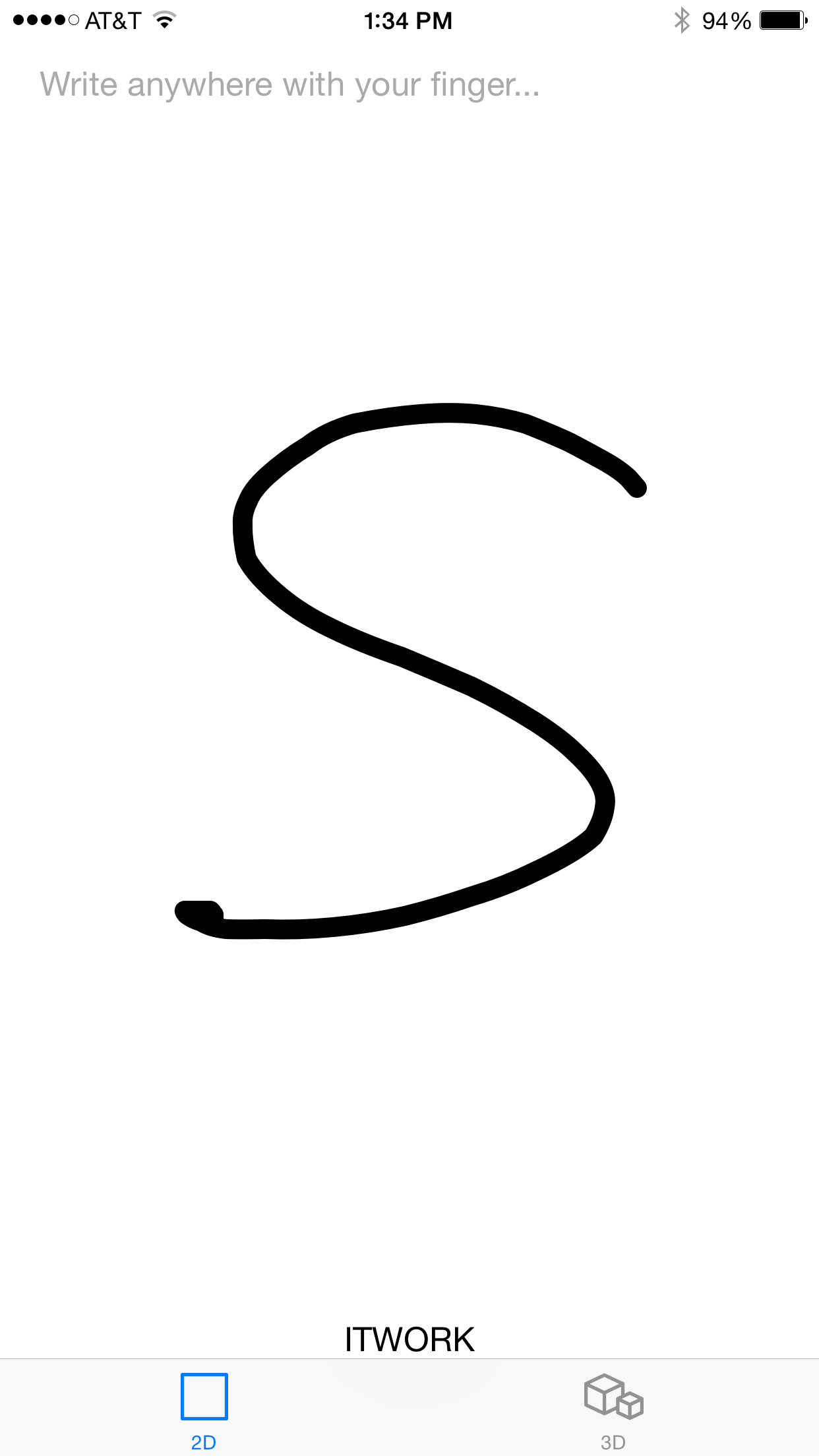
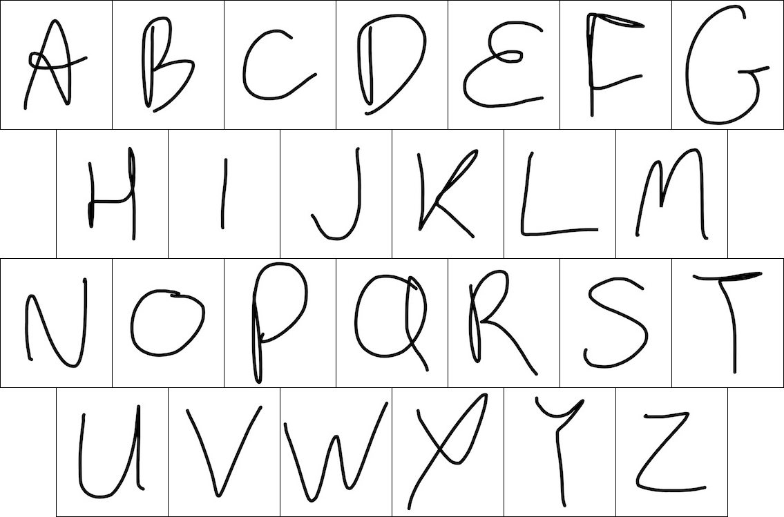
Here are some examples of our handwriting. If yours is very different, you may not have much success getting it to be recognized unless you retrain the perceptron algorithm with your own data. Don't forget, our naïve app expects that one stroke = one letter, so don't lift your fingertip until the letter is finished.
In Section 1, you've worked with a very particular machine learning solution. It involved computing an ad hoc set of features, feeding them to a particular classifier algorithm, and combining the output of that algorithm with live data in just the right way so as to get an immediate result.
Note that this is one of very many possibilities. If you'd like to explore alternatives in any part of this process, extra credit is available. For instance, you might try scaling x and y differently to bring each character into a more uniform aspect ratio — being careful that your new code does not make recognition stop working for tall, thin characters like "I". Or you could find out what happens when the stroke is sliced up into 4×4 squares or more, rather than 3×3. You could also make changes to the app to support gestures consisting of more than one stroke, for instance by keeping additional state in instance variables of the GestureProcessor object, and not calling gestureProcessor:didRecognizeGesture: right away. You might consider learning how to work with delays and asynchronous processing on iOS in order to trigger recognition when no new strokes have been added for a few hundred milliseconds.
For this section, you will convert acceleration reported by the phone into an appropriate coordinate system where it can be integrated over time. You will observe some pitfalls of this procedure, and consider how to mitigate them.
iOS will report "device motion" (i.e. pre-fused sensor readings from the accelerometer, gyroscope, and compass) at up to 100 Hz. As you know, acceleration is the rate of change of velocity, and velocity is the rate of change of position, so in principle we can recover relative position by integrating the acceleration twice. This data source is not really suitable for double-integrating to get position, but we're going to try it anyway and see what we get.
We're going to rely on CoreMotion to track rotation of the phone over time, while using gravity and the Earth's magnetic field to keep the gyro from drifting (otherwise, it would totally lose its orientation over the course of a few minutes). CoreMotion will also do its best to work out which portion of the accelerometer signal is due to "user acceleration" versus gravitational acceleration, and it will report these parts separately. However, the iPhone accelerometer is designed for making the UI rotate when the phone rotates, not for tracking user motion while being swung through the air. If reports from other developers are to be believed, the iPhone configures its accelerometer for 2 g's maximum acceleration. This means that anything more than sedate walking motion will exceed the sensor's range. If the sensor reports an out-of-range signal for a period of time, then we don't know the area under that part of the curve, and our integral will be off — and our double integral doubly so. The way we will observe this is that swinging the iPhone and bringing it back to its starting position may produce what appears to the software to be a net change in velocity. This net change in velocity leads to unbounded growth of the estimated position over time.
This is not ideal. From the perspective of control theory, what is happening is that the integrator is an unstable linear system: it does not exhibit the bounded-input, bounded-output property, because the integral of a finite constant taken over a suitably long interval will eventually exceed any bound. We need to stabilize the integrator, because users expect that the phone will not "fly off to infinity" in its own imagination and thus suffer loss of gesture recognition capability. We can do this by moving poles on the S-plane. If you're not into control theory, this will be the same as filtering out the DC component of the position and velocity, in order to prevent them from increasing forever. Unfortunately, this technique leads to other funny behaviors, like the phone getting confused if a gesture takes too long.
iOS provides device motion through the
CMMotionManager,
which is instantiated for you by the Gesture3DViewController like
this:
var motionManager: CMMotionManager = CMMotionManager()

motionManager.deviceMotionUpdateInterval = 1e-2

motionManager.startDeviceMotionUpdates(
    using: .xArbitraryCorrectedZVertical,
    to: OperationQueue.main) { [weak self] (motion, error) in
        self?.accumulateMotion(motion)
        }
This will result in periodic calls to Gesture3DViewController's
accumulateMotion: method, which will be the subject of Tasks
2A-2C.
The contents of a device motion update are attitude (the orientation of the device relative to the "reference frame"), rotation rate (rate of change of attitude), gravity (CoreMotion's best guess of the portion of accelerometer output which is due to the Earth), userAcceleration (the remainder of the accelerometer output), and magneticField (the external B field acting on the device).
We will only be using attitude and userAcceleration; these are the fields we need to determine the device's movement in three-dimensional space. iOS provides userAcceleration in instantaneous device coordinates:
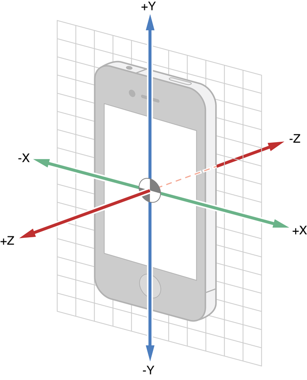
You can find this, and more information about the coordinate systems of the data, in Apple's documentation.
In order to talk about devices that can not only move but also rotate through all different orientations in three dimensions, we need a quantitative way to talk about rotations and orientations. We will consider rotations first. If you are already familiar with this material, you are of course welcome to skip down a bit.
Rotation is a physical process which proceeds continuously from a start point to an end point. When we refer to rotations, however, we will think of them as operations, or functions, which map un-rotated inputs to rotated outputs, skipping over any intermediate states. We refer to the "family" of rotations as the set of all such operations. For instance, the "identity" rotation, I, has its output always exactly equal to its input. You can think of this as a rotation by zero degrees. The family of rotations includes a 90-degree rotation to the left, and an 89-degree rotation, and an 89.999999-degree rotation. Thus, the family of rotations is an infinite set, just as the real numbers are an infinite set.
When you rotate your head, your eyes move relative to your surroundings. In three dimensions, we distinguish between translations, which move every part of an object laterally while preserving its orientation, and rotations, which move each part of an object relative to some origin, but preserve the location of this origin. Other types of transformations are possible in the real world, but rotations and translations are the only kinds which do not involve any amount of bending or stretching. As an abstraction for physical objects which can be neither bent nor stretched, we refer to rotations and translations as the full set of "rigid body motions". We could allow the origin of the rotation to vary, but this turns out to be no different than mixing translations and rotations, so we will fix the origin with no loss of generality. You can think of it as the center of the phone.
Rotations can be composed as functions. Just as f(g(x)) refers to the output of f when its input is g(x), R2(R1(x)) is the output of rotation R2 when acting on the result of R1 acting on x. With functions, we can use f(g(x)) = (f ∘ g)(x) to define a new function, f ∘ g, which takes inputs directly to outputs, skipping the intermediate step. Similarly, we can consider R2 ∘ R1 as a new rotation, without any reference to x. From now on, we will drop the "∘" symbol, and write simply R2R1.
Just as functions do not, in general, have the property f(g(x)) = g(f(x)), as we can check by comparing e.g. the graphs of sin(x2) and sin2(x), so rotations do not in general satisfy R1R2 = R2R1. There are special cases, but you may find it helpful at this point to file away the fact that general rotations are not commutative.
Note that composing any rotation R with the identity I gives the same rotation that we started with: whether we compose them as RI or IR, we have RI=IR=R, because I returns its input unchanged. This is one of those special cases we mentioned: I commutes with any rotation.
Rotations can also be inverted as functions. R-1(R(x)) is identically x. We can therefore define inversion by requiring R-1 R = I. On physical grounds, it is clear that the inverse of a rotation is also a rotation, because we can always restore a rotated object back to its starting orientation without bending, stretching, or translating it. It's also good to note that composition of rotations is associative; that is, (R1R2)R3 = R1(R2R3).
We have now encountered four properties of the set of rotations under composition — closure (the fact that the composition of two rotations is a rotation); associativity; identity (the existence of a rotation I that leaves any other rotation unchanged under composition); and the existence of an inverse rotation for any given rotation. These are the defining properties of a group structure; from now on, we will talk about the group of rotations instead of the set or family, to emphasize that rotations obey these particular algebraic laws. Occasionally, in other contexts, you will hear the group of rotations in three dimensions referred to as SO(3), or the special orthogonal group.
We've stated that the group of rotations consists of transformations which neither bend nor stretch an object, and leave the origin unchanged. An additional property of each individual rotation is that it must leave not just one, but infinitely many points unchanged along a line through the origin. This line is called the axis of the rotation, and the plane at right angles to this line is called the plane of rotation.
In introductory treatments of rotations, it's common to see emphasis placed on the axis of rotation, and on constructing e.g. the rotation that operates about a given axis by a given angle. It turns out, though, that this notion of rotating about an axis is not fundamental to rotations, but rather to the three-dimensional space in which we live. To see this, consider rotations in two dimensions by an angle φ. In polar coordinates, these transformations map points (r,θ) to (r,θ+φ).
If we try to draw the axis of this rotation, we will be forced to draw a line perpendicular to the two-dimensional plane we're working in. We can do that, because we're three-dimensional. But that's cheating, because it introduces three dimensions in an attempt to explain a fundamentally two-dimensional concept. Really, there are zero lines in two dimensions perpendicular to the plane of rotation. The problem is worse in four dimensions, where rather than zero axes of rotation, we have infinitely many.
The more general concept is the plane of rotation, which is meaningful in any space of dimension two or more. So instead of a rotation about the z axis, we'll be persnickety and talk about a rotation in the x-y plane.
From geometry, we know that it is always possible to break apart a vector in three dimensions into a component in the plane of rotation and a component perpendicular to the plane. We can understand the action of a rotation on a vector by allowing it to act on each of these two component vectors separately, and then adding the results back together.
For the component in the plane, we can see the behavior very simply in polar coordinates. The radial coordinate of a point, measured relative to the origin, should be unchanged by a rotation, and the angular coordinate should increase by the angle of the rotation. We can therefore write the action of the rotation on the component in the plane as (r,θ) → (r',θ') = (r,θ+φ).
On the component perpendicular to the plane, as we have mentioned, the rotation does not act at all. So we can write the action of the rotation on this component as Z → Z' = Z.
If rotations had no further properties than those of functions in general, we'd have no hope of representing all of them in a finite amount of memory. Fortunately, the group of rotations is extremely restrictive compared to general functions. Based on the preceding discussion, we can immediately state that given the plane of rotation (specified, for instance, via its normal vector) and the angle of the rotation (where we have to be careful to define which direction is plus and which is minus), the rotation's action on all points, in and out of the plane, is fully determined: on the vector component perpendicular to the plane, the rotation does nothing; and on the component in the plane, the rotation alters the polar coordinates of the point by an angle addition. So we don't need more than four numbers (normal vector plus angle) to specify a rotation.
In fact, observing that the normal vector always has unit length, and that negating both the normal vector and the angle of the rotation gives the same rotation as before, we can be even more concise. We can specify just the three components of a vector whose length is the absolute value of the angle and whose direction specifies the (oriented!) axis of rotation. The action of such a rotation on any vector can be evaluated using a little bit of vector algebra. For those who want to chase this rabbit a little further, you are welcome to read up on the exponential map, which expresses the relationship between this axis-angle representation and the group of rotations. You are doubly-welcome to read up on spherical linear interpolation, which goes by the (charming) name "slerp".
There are many other formalisms for representing the group of rotations, including 3×3 matrices of determinant 1 with the property that their columns (respectively, rows) are mutually-orthogonal and of unit length; Euler angles; quaternions; and so forth. One reason for the proliferation of alternatives in this space is that for any given choice, it is usually either painful to compute the action of the rotation on a vector, or it is painful to compose rotations together into a new rotation, or it is painful to keep track of the accumulation of many small rotations over time due to numerical round-off errors, or it is painful to invert a rotation. Or, if you're very lucky, there are situations where the coordinates "seize up" in the sense that nearby rotations no longer have nearby coordinates (see gimbal lock).
For this lab, you will be using quaternions. Quaternions share many properties with complex numbers, and can be thought of as a real number plus an imaginary vector. These objects therefore have four components. Rotations are specifically represented by quaternions whose squared components sum to 1, the so-called unit quaternions. These are related to the axis-angle representation discussed earlier by
qw = cos(φ/2)
qx = nx sin(φ/2)
qy = ny sin(φ/2)
qz = nz sin(φ/2),
where the vector n is normal to the plane of rotation, and φ is the angle of rotation. The rules for multiplying quaternions by quaternions and applying quaternions to vectors are somewhat tedious; fortunately, you can call subroutines for that.
Because there is no notion of absolute orientation in the laws of physics, we
always measure an object's orientation relative to some "standard"
orientation. In our case, we specified the standard orientation when we passed
the constant
.xArbitraryCorrectedZVertical
to CoreMotion. The orientation of an object, then, can be represented by the
rotation which translates vectors from the object's (instantaneous) local
coordinate system to the corresponding vectors in the (persistent) coordinate
system of a hypothetical copy of the object in standard orientation. This
rotation is precisely the value returned by the CMDeviceMotion's
attitude property.
accumulateMotion:accumulateMotion: will need to convert the data from iOS into a
consistent set of coordinates, track the user's motion over time, and hand off
the data to be stored and eventually transmitted to the
GestureProcessor. Here's the outline of
accumulateMotion that you will start with, which you can find in
Gesture3DViewController.swift under InertialMotion/User Interface in Xcode's project
navigator.
func accumulateMotion(_ motion: CMDeviceMotion?) {
        guard let motion = motion else {
            return
        }

        let dt = motionManager.deviceMotionUpdateInterval
        let attitude = GLKQuaternionFromCMQuaternion(motion.attitude.quaternion)
        let userAcceleration = GLKVector3FromCMAcceleration(motion.userAcceleration)

        // -- TASK 2A --
        var acceleration: GLKVector3 = userAcceleration
        // rotate acceleration from instantaneous coordinates into persistent coordinates

        // -- TASK 2B --
        // integrate acceleration into velocity and velocity into position

        // -- TASK 2C --
        // apply your choice of braking to velocity and position to stabilize the integration loop

        // add the new data to the log

        appendPoint(position, attitude: attitude)
    }
appendPoint will store the data while the user is
touching the screen, and when the user stops touching the screen, it will call
the GestureProcessor's
processGesture3DWithSamples method, which will be
the subject of Section 3.
GLK is short for GLKit, which is an Apple framework (library) intended to make OpenGL programming easier for 2-D and 3-D graphics. We're using it here and elsewhere because it provides a fairly complete set of vector/matrix manipulation functions. We've catalogued a few of these functions for you, but you can find the full set through Apple's documentation.
Your first task in accumulateMotion
will be to use the quaternion stored in attitude to convert the
vector acceleration into a persistent set of coordinates that do
not vary with the orientation of the phone. Fortunately, there's a function in
the appendix which will do this for you in one step.
Yes, we're going to make you hunt for it. You'll know it when you see it. Note
well that none of these functions modifies the variable you pass in; they return
new objects, which you will have to assign back to the variable you wish to
modify.
For reasons which would totally be hilarious if we knew what they were, you
will also want to negate acceleration at this point (otherwise the
visualization will look wrong later). It does not matter whether you do this
before or after applying the rotation. You can negate all the components of
acceleration manually (you'll have to look up the names of the
components of the GLKVector3 structure in the headers, for instance
by command-clicking on "GLKVector3" somewhere that it appears in the code), or
you can use the function listed in the appendix that multiplies a vector by a
scalar to multiply by -1.0.
Note that we could have hidden this step from you by negating the vector somewhere else in the app. But you may find that no matter how careful you are in working with coordinate systems in mobile programming, sooner or later you will encounter a minus sign or something similar that you can't track down. You can either spend a lot of time reasoning about how all the components of your app work together to produce the issue, or you can fix it in an ad hoc way like we are doing here. Unfortunately, if you use more than one or two such fixes, you can quickly get into a situation where there are 2n possible ways to flip all the unexplained bits in various parts of your program, and you can't find an assignment that works. This is an example of technical debt. When you're working on a larger project than this simple app, you'll have to factor that future possibility into your decision to make a quick fix versus tracking down the real problem.
Extra credit is available to anyone who can explain to our satisfaction why there is a minus sign here.
We can write down a set of differential equations for the position and velocity in terms of the acceleration as follows:
where we use bold to denote vector quantities. A simple and inaccurate (but often acceptable) way to solve these equations is the Euler method. To apply this method, we replace the infinitesimal quantities in the differential equations with finite differences, and rearrange:
and hence
Actually, it would be more accurate to split the velocity update into two parts, because a constant acceleration acting for time should give a change in position of . You can check for yourself that the method above erroneously yields a change in position two times larger.
The procedure outlined here has allowed us to take a continuous-time system of (ordinary) differential equations and turn it into a discrete-time integration rule using a small, finite number of additions and multiplications. This is just a glimpse of a rich field.
Your job for this task is to translate this math into code in
accumulateMotion. The
Gesture3DViewController already has instance variables called
velocity and position that you should use for this
purpose, and we've initialized a variable dt with the expected time
between updates. You can change the code to set dt to the actual
time between updates if you wish, using e.g. motion.timestamp. If you choose to
do this, you'll have to introduce a new instance variable to hold the last
timestamp, and you'll have to include logic for doing the right thing when the
first sample comes in. The vector manipulation functions in the appendix are likely to be useful for this task.
As we've discussed, an integrator like the linear system you implemented in task 2B is unstable in the sense that a bounded input acceleration can lead to an unbounded output position estimate. In fact, for a constant nonzero input, we would expect to see quadratic growth in the output position. Among the undesirable properties of such a system is the way that small errors in the acceleration lead to large errors in the estimated position. You need to tweak your code from task 2B to stabilize the system. Feel free to adopt any of the following approaches, or to develop your own.
If you choose to develop your own approach, keep in mind that data is always noisy and models are always incomplete. You want your system to be "robust" in the sense that the behavior of the app right now depends little or not-at-all on questionable input from the distant past. That is, think of bad data as water under the bridge. Don't let its effects on your program's state linger forever.
At this point, you should be able to draw ribbons in the air by tabbing over to the 3D screen and moving/rotating the phone while touching the screen. We will check that you have stabilized the integration loop by waving the phone vigorously in the air, and then watching to see if the computed position flies off to infinity or stays finite. It's fine if your app needs a few moments to recover.
You should be able to make recognizable 3-D shapes, like squares, triangles, circles, checkmarks, and x's, using your app. If you cannot draw shapes, check your work and come talk with us.
The acceleration data provided by CoreMotion seems to have some start-up transients, which can throw off your integration for a long time after start-up. You are welcome to invent a solution for this problem.
For this section, you will reduce the 3-D gesture recognition problem to the 2-D case. With any luck, you'll soon be recognizing letters formed by waving the phone in the air while touching the screen.
You will be working on
processGesture3DWithSamples, which you can
find in GestureProcessor.swift. Here's the initial skeleton.
    func processGesture3D(samples samples3D: [Sample3D], minSize: Double) {
        var samples2D = [Sample2D](repeatElement(Sample2D(x: 0.0, y: 0.0, t: 0.0), count: samples3D.count))

        // -- TASK 3A --
        // Estimate left-right, up-down axes by averaging orientation over time:
        var M = GLKMatrix3()
        // For each i, convert samples[i].attitude to a 3x3 matrix and sum it into M.
        // Then find the rotation matrix most similar to the resulting sum.

        // -- TASK 3B --
        // Project points to 2D:
        // For each i, form the matrix-vector product of M with samples[i].location
        // and copy the transformed x and y coordinates, along with the timestamp,
        // to samples2D[i].

        // Apply 2-D solution
        processGesture2D(samples: samples2D, minSize: minSize)
}When the user makes a gesture in the air with their phone, they have a mental picture of whether they are moving the phone left or right, up or down. For instance, if the user holds the phone out in front of them, then up-and-down gesturing will correspond to motion in the vertical dimension. If, however, the user is hunched over the phone (and hence is looking downward towards the screen), then the phone's long axis, and the user's notion of up-and-down gesturing relative to the screen, will be horizontal.
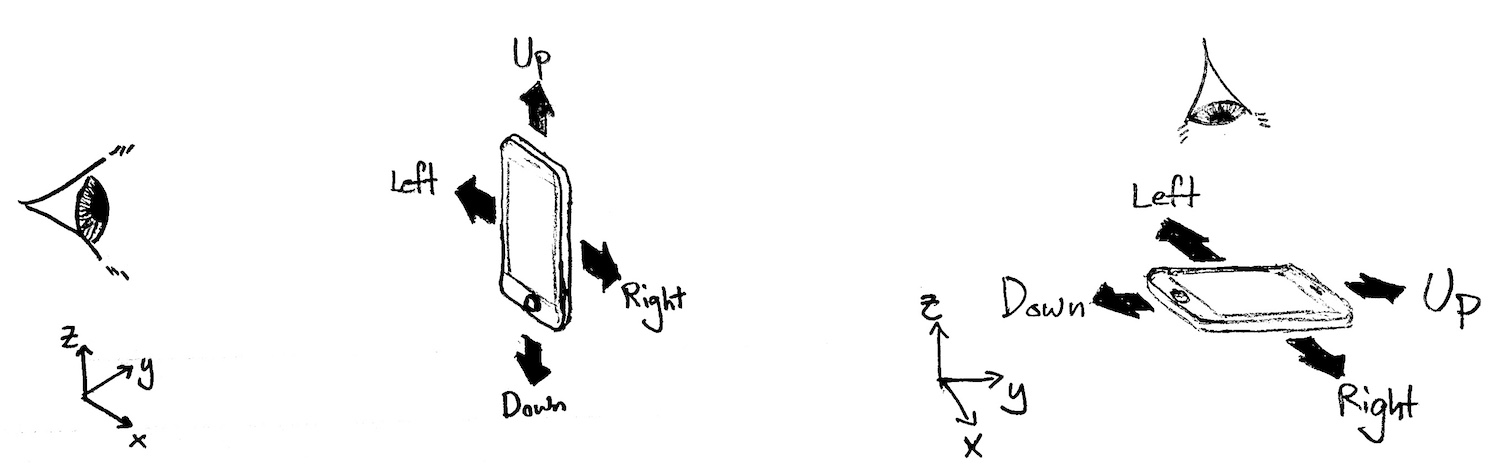
Since the user is free to change posture (and hence the orientation of the phone) at any time, but is not likely to do so in the middle of a gesture, we can average the orientation of the device during the gesture to guess what the user is currently thinking of as the up-down and left-right axes.
We also recall the definition of the instantaneous device coordinate system:
Your job for this part is to use the attitude (that is, orientation) quaternion
recorded in each of the 3-D motion samples in
processGesture3DWithSamples
to estimate the instantaneous orientation of the phone's y-axis — a proxy
for the user's notion of up and down — and the phone's x-axis — a
proxy for the user's notion of left and right.
What we are doing here is to determine the average of the phone's orientation over the period of the gesture. However, what it means geometrically to average orientations together is a bit ambiguous. To visualize this, suppose that we were averaging orientations (rotations) in two dimensions. What is the average of a 359-degree rotation and a zero-degree rotation? It's certainly not a 179.5-degree rotation, which is farther from either of the two inputs than they are from each other. We could say that the average is a 359.5-degree rotation, but then what is the average of a 90-degree and a 270-degree rotation? Or what is the average of a group of four rotations by angles 0, 90, 180, 270 degrees?
A
rigorous treatment of this issue
is available, invoking some heavy-duty linear algebra which we will not require
you to study. Instead, we've provided you with a function,
NearestRotation in Geometry.swift, that will call into iOS's
implementation of the Netlib Linear Algebra PACKage (LAPACK), an exceedingly
popular and well-maintained library. LAPACK is, unfortunately, written in
Fortran with an interface consisting of six-character function names like
dgesdd.
We wouldn't deny you the pleasure of reading the code behind that marvel, or of
studying the
technique it implements. For our purposes, what you need to know is that
the average of a set of rotations can be taken to mean the result of a
three-step procedure:
The final result can be converted back into a quaternion, or used directly in
matrix form. Step 3 is what NearestRotation does.
The final task for this lab is to project the coordinates of the 3-D sample
points to 2-D coordinates suitable for use by
processGesture2DWithSamples.
In the code, you
will need to form the matrix-vector product of the rotation matrix M
from Task 3A with samples3D[i].location for each i, and then
copy the transformed x and y coordinates, along with the timestamp
samples3D[i].t, into samples2D[i].
The gesture recognition results that we have obtained using the procedure we have outlined for you have not been fantastic. One reason for that is the poor fit between the sensor data (acceleration) and the machine learning features (position, motion, and dwell time). We would like to encourage you to think about an alternative set of machine learning features which are a more direct fit to the 3-D motion problem and the accelerometer data. Let us know what you discover!
You may find the following functions, macros, and data types useful for the exercises in this lab. It's better to use system-provided functions and data types rather than defining your own because the result will (usually) be more concise, readable, performant code.
| Name | Description |
|---|---|
min(a, b) | This is actually a preprocessor macro that works on any data type. It's smart enough to only evaluate its arguments once,
which is not true of the naïve way of writing such a macro, (((a) < (b)) ? (a) : (b)), which might evaluate each argument
twice if the compiler can't convince itself that they are side-effect free. |
max(a, b) | Same story. Contrast these macros with fmin/fmax/fminf/fmaxf, which require the programmer to use a different function for each data type. |
exp(x) | Returns the double ex. |
NSDate.timeIntervalSinceReferenceDate() |
Returns number of seconds (including fractional part) since a particular fixed date in 2001. Note that the return value is a double, a 64-bit floating-point (e.g. scientific notation) data type. Of those 64 bits, a certain number are used for the exponent, so in effect, a double has 53 significant bits (analogous to significant figures in base 10), and when used to store the time interval since the reference date, gives a resolution of ±26 nanoseconds. However, if you cast the double returned by this function to a float (32 bits) or store it in a variable of type float, you will lose bits, leaving only 24 significant bits. This leaves you with a resolution of ±14.1 seconds — so don't use float to represent time intervals; stick with double. |
GLKVector3 | A three-dimensional vector data type. Its members can be accessed with .x, .y, .z. |
GLKVector3Make(x, y, z) | A helper function which returns a GLKVector3 with the specified coordinates. |
GLKQuaternion | A four-dimensional vector data type useful for representing rotations in three dimensions. |
GLKVector3Add(a, b) | Returns the element-wise sum of two vectors. |
GLKVector3Subtract(a, b) | Returns the element-wise difference of two vectors. |
GLKVector3MultiplyScalar(a, b) | Returns a vector whose components are the scalar b times the components of a. |
GLKVector3Normalize(a) | Returns a / |a|. |
GLKQuaternionRotateVector3(q, a) | Returns the result of applying the rotation represented by q to a. |
GLKVector3DotProduct(a, b) | Returns the sum over components of the element-wise product of a and b. |
GLKMatrix3 | A 3×3 matrix data type. See its definition for details. |
GLKMatrix3MakeWithRows | Accepts three vectors and returns a 3×3 matrix. |
GLKMatrix3MultiplyVector3(M, a) | Returns the result of a matrix-vector product. |
GLKQuaternionFromCMQuaternion(motion.attitude.quaternion) | Our helper function which converts between CoreMotion's rotation data type and GLKit's. |
GLKVector3FromCMAcceleration(motion.userAcceleration) | Our helper function which converts between CoreMotion's acceleration data type and GLKit's vector data type. |